This essay outlines the process followed for a recent Wi-Fi design project I completed for a single-floor office in a multi-tenant building in London.
The design process has the following steps:
- Information Gathering
- Establish Requirements
- On-site Survey
- Data analysis and RF environment creation
- AP Placement
- AI Survey
- Report Creation
- Information Gathering
The customer requested a wireless survey. A survey can mean different things to different people, so to narrow this down the customer was asked to complete a wireless survey questionnaire. This questionnaire is designed to capture why the customer has requested a survey, details about the site and potential usage of the network, and what they hope to get out of the survey. In this case the customer has bought new office premises and would like to extend their current wireless network to include these offices. I conducted with the customer to clarify details such as, how they will use the new office space, number and types of client devices, preferred AP model etc, and arrangements for the on-site survey.
I used the information gathered to define the survey requirements. The table below shows the minimum requirements the wireless networks should fulfil. The survey results presented in this document are assessed based on these network requirements. These requirements align to high-performance data and voice.
| 2.4 GHz | 5 GHz | 6 GHz | |
| Minimum Signal Strength | -65dBm | -65dBm | -65dBm |
| Minimum Secondary Signal Strength | -67dBm | -67dBm | -67dBm |
| Channel Overlap | 2 @ -86dBm | 1 @ -86dBm | 1 @ -86dBm |
- On-Site Survey
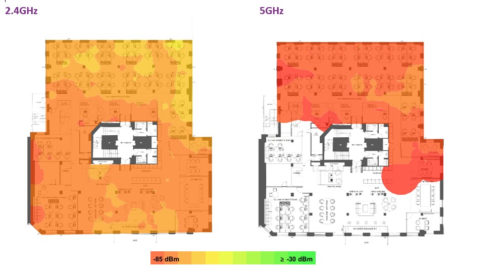
The first step of the on-site survey was a survey of the existing RF environment. This includes all neighbouring APs and RF interferers. The results showed that the existing RF environment is very quiet. The 2.4GHz is mostly under -75dBm, 5GHz is mostly under -80dBm, and 6GHz had no signals detected at all.
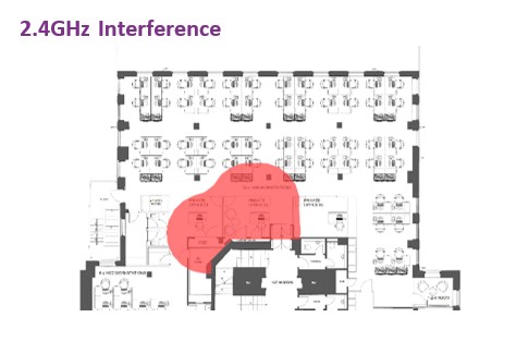
A low level of RF interference was detected near the central stairwell. This was likely to be originating from a microwave oven on another floor. Due to the low level and low area affected I decided to not investigate this further.
Next a sample of AP locations were simulated using an AP on a stick. The primary reason for this testing was to establish how RF energy propagates though certain absorption obstacles such as walls, glass panelling, and furniture. The following are results of the sample AP testing.
- Data analysis and RF environment creation
The on-site survey data was then used to create a simulated RF environment. The propagation loss was measured through the different wall and furniture types. This was done by taking the difference in measured signal strength in several locations on either side of the absorption object. The average dB loss for 2.4GHz and 5GHz was then used to draw the object in the Ekahau Wi-Fi design tool. The difference signal absorption between signals in the 2.4GHz and 5GHz spectrum was then used as an estimate for the difference in signal absorption between signals in the 5GHz and 6GHz spectrum.
The AP placement design could then be applied to this environment for 2.4GHz, 5GHz and 6GHz. The AP used in the design was the Cisco Meraki 9166i.
- AP Placement
I used the following considerations to design the AP placement to best meet the requirements.
Events Space
AP01 is located in the centre of the events space. This AP provides coverage and capacity when the area is used as a breakout area. When the area is used as events space with approximately 100 users, AP02, AP03 and AP08 will provide additional coverage and capacity.
Roaming Pathways
AP04 and AP06 are positioned to provide coverage along the corridors and ensure smooth roaming. AP01 and AP05 are positioned in line of sight of the entrances to ensure clients are connected as they enter the office space.
Meeting Rooms
AP02 and AP03 provide coverage and capacity to the meeting rooms. Coverage to the smaller meeting rooms is provided by APs AP05 and AP06.
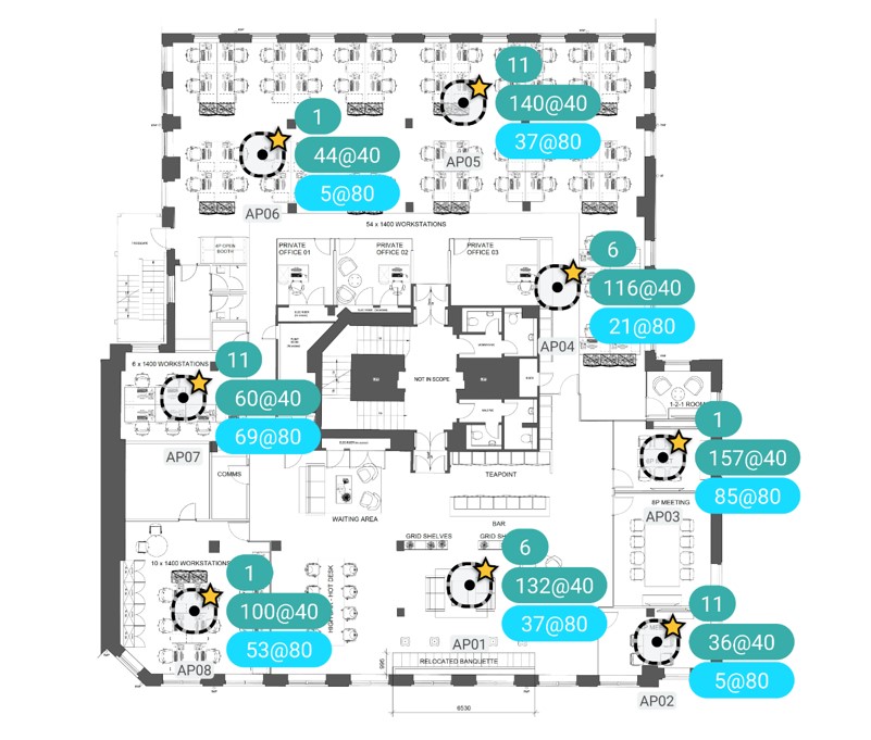
Recommended AP Locations
A total of 8 APs were recommended. The following graphic shows the recommended AP locations along with a suggested channel plan for 2.4GHz, 5GHz and 6GHz.
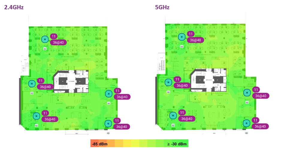
The following heat maps were provided to show the coverage as simulated using the RF environment created and recommended AP placement.
- AP Locations
This drawing shows the locations of the recommended Meraki APs along with their channels configured. Location photos are also provided later in the document.
- Signal Strength
Signal strength is the most basic requirement for a wireless network. A stronger signal allows for more complex modulation techniques and therefore more throughput.
- Secondary Signal Strength
Secondary Signal Strength shows the second strongest signal at any given location on the map. This shows the resilient coverage in the event of an AP failure and indicates the amount of cell overlap to ensure smooth roaming.
- Channel Interference
Channel interference indicates the number of access points overlapping at each location in a single channel. Channel interference can reduce capacity as Wi-Fi devices have to share the capacity of a single channel. Due to the low numbers of APs and low neighbouring networks. The channel plan can allow for channel bonding whist still keeping interference to a minimum.
The final stage was to create a report to outline the survey and design process. The report contained the following sections:
- Introduction
Outline of the purpose of the survey.
- Survey Scope
Define the area of the survey and the site details.
- Network Performance and Coverage Requirements
Define the requirements to which the survey is measured against.
- Executive Summary
Bullet points of the main observations, recommendations, and design considerations.
- Bill of Materials
Define the additional hardware required to achieve the design.
- Site Survey Results
On-site survey and AI survey results
- AP Placement Details
Detailed Information including photos, primarily intended to communicate the recommendations onto the installation team.
